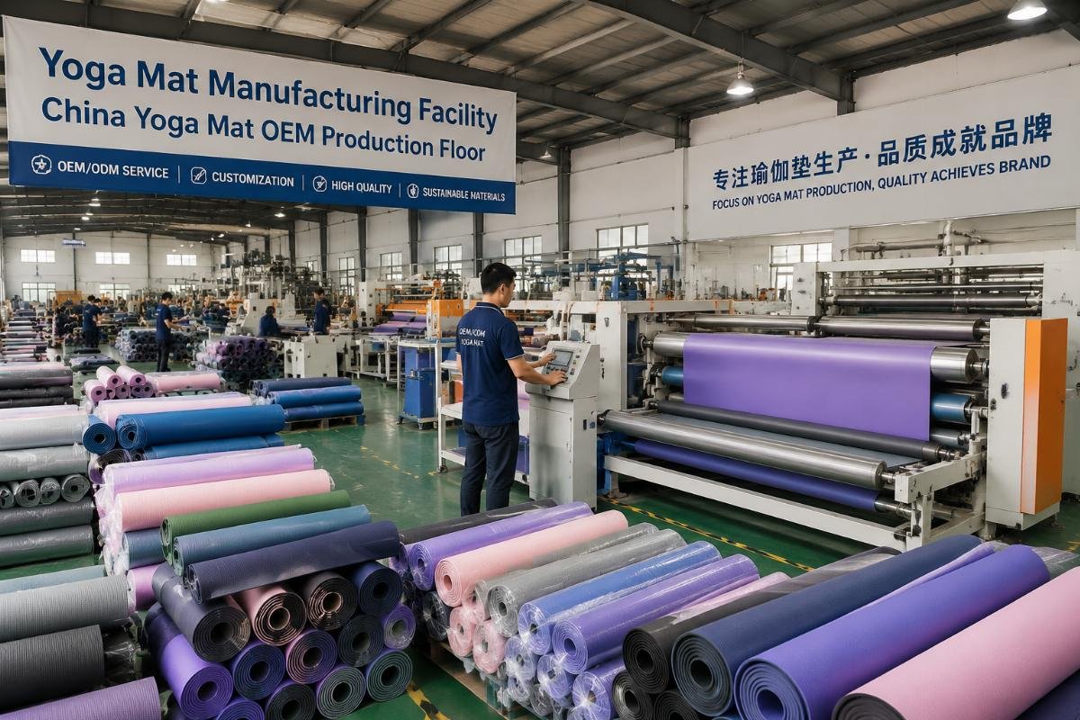
What does a global smart fitness mirror technology list really tell you about production risks?
You're comparing supplier quotes for smart fitness mirrors, and the spec sheets look nearly identical—same resolution, same reflectivity, same claimed lead time. Then six weeks into production, you discover the coating process can't scale, the display needs a redesigned power supply, or the sensors won't sync with your chosen AI chipset. The problem isn't the technology list itself. It's what the list doesn't show you: the procurement risks hidden inside every technical choice.
A smart fitness mirror technology list isn't a feature comparison chart—it's a map of cost structures, supplier dependencies, and production bottlenecks you won't see until your deposit is already wired. Understanding which technical parameters connect to which manufacturing trade-offs determines whether your project ships on time or stalls in quality control for three months.

Most buyers treat the technology list as a checkbox exercise. That approach works for commodity components. Smart fitness mirrors aren't commodity components—they're integrated systems where every choice locks you into a specific supply chain path, and those paths have very different risk profiles.
Why do two suppliers with identical display specs deliver completely different production outcomes?
When you see "4K LCD with 90% reflectivity" from two different suppliers, you're looking at the same words describing different realities. One supplier might use a panel binned for high transmittance uniformity with a mature two-way mirror coating process. The other might use a standard bin panel with an experimental coating that works in samples but fails consistency tests in volume production. The spec sheet shows you the target numbers. It doesn't show you the process maturity that determines whether you'll actually hit those numbers at scale.
In procurement scenarios we've encountered, the most common cause of delayed deliveries isn't component shortages—it's discovering too late that a "cheaper equivalent" display module requires completely different calibration procedures1, thermal management solutions, or quality control thresholds that the original quote didn't account for.

What the reflectivity percentage doesn't tell you about coating supply chains
Reflectivity is listed as a single percentage on every spec sheet. Behind that number sits a coating process with its own lead time, minimum order quantity, defect rate, and supplier dependency profile. A 90% reflective coating from a mature process line might cost more per square meter but ships consistently with predictable yield rates. A 90% coating from a newer supplier might look identical in samples but comes with 8-week lead times, batch-to-batch variation that affects calibration, or dependency on a single factory that becomes your production bottleneck.
We've seen projects choose the lower-cost coating option and then discover three months later that every production batch requires individual calibration adjustments because the coating uniformity varies by ±3%—not enough to fail inspection, but enough to make every mirror look slightly different under identical lighting conditions. That variance doesn't show up in the technology list. It shows up when your QC team starts flagging units and you're trying to figure out why your rejection rate is triple the forecast.
| Coating process maturity | Typical lead time | Batch consistency | Integration risk |
|---|---|---|---|
| Established multi-factory process | 3-4 weeks | ±1% variance | Low—predictable calibration needs |
| Single-source proven process | 5-6 weeks | ±2% variance | Medium—supplier dependency risk |
| New process under scaling | 7-10 weeks | ±3-5% variance | High—calibration and QC complexity |
The technology list shows you reflectivity specs. Your production schedule depends on which coating supply chain backs up those specs.
How does display panel type actually affect your power supply budget and thermal design?
Buyers see "display options: LCD / OLED / Mini-LED" and evaluate based on image quality and unit cost. What the list doesn't make explicit: each panel type comes with completely different power requirements and heat dissipation profiles that ripple through your entire product design and BOM.
LCD panels under reflective coatings need significantly higher backlight power to maintain acceptable brightness for fitness content2, which means larger power supplies, more heat generation, and potentially active cooling solutions that add cost, weight, and noise. OLED panels avoid the backlight problem but come with higher unit costs, longer lead times, and more restrictive supplier options3. Mini-LED offers a middle path but requires more complex driver circuitry and tighter thermal management.

Why the backlight power spec connects directly to your mechanical design constraints
An LCD module rated at 400 nits might need 50% more power to deliver acceptable brightness through a reflective coating4 compared to direct display applications. That power increase doesn't just show up in your electricity bill—it shows up in component costs across the entire assembly. You need a bigger power supply, which means more internal space allocation and higher shipping weight. You generate more heat, which might require active cooling fans (adding noise and failure points) or aluminum heat sinks (adding cost and manufacturing steps).
Based on feedback from production lines, one of the most common mid-production surprises is discovering that the chosen display's power requirements exceed what the original mechanical design can accommodate. The solution isn't just "use a bigger power supply"—it's a cascade of design changes affecting the housing dimensions, mounting structure, safety certifications, and shipping specifications. These changes don't just cost money. They cost time, and in contract manufacturing time delays trigger penalty clauses.
| Display technology | Backlight power requirement | Heat dissipation need | Typical BOM impact |
|---|---|---|---|
| Standard LCD | High (150-200% of direct use) | Significant—often requires active cooling | +$45-80 in power supply and thermal components |
| OLED | None (self-emissive) | Minimal—passive cooling usually sufficient | +$120-180 in panel cost, saves cooling budget |
| Mini-LED | Medium (120-150% of direct use) | Moderate—heat sink usually sufficient | +$60-95 in driver circuitry and thermal management |
The technology list shows you panel options. Your mechanical team needs to know what those options mean for the entire system integration.
What does sensor fusion actually cost in production time versus component price?
Every smart fitness mirror technology list includes sensors: camera, depth sensor, maybe an IMR unit for pose detection. The list shows component specs. It doesn't show you the integration complexity—the software, firmware, and hardware coordination work that determines whether these sensors actually function as a system or just as a collection of parts that work individually but fight each other in production.
In typical OEM scenarios, sensor integration costs more in engineering time and production delays than in component pricing5. A cheaper sensor suite with mismatched frame rates, incompatible SDK versions, or poor thermal isolation can add months to your time-to-market and thousands of dollars in debugging costs that never appeared in the original quote.

Why frame synchronization problems don't appear until mass production
In prototype builds, you can manually calibrate sensor timing, adjust frame rates in software, and work around synchronization issues through one-off fixes. Those workarounds don't scale. In mass production, every unit needs to ship with sensors that lock together automatically, maintain sync under temperature variations, and recover gracefully when one sensor temporarily drops frames.
We've encountered projects that chose sensor components based purely on per-unit cost, assuming integration would be straightforward because the suppliers claimed "plug-and-play compatibility." The reality: the camera sensor and depth sensor had different master clock requirements6, the AI chipset couldn't process both data streams simultaneously without frame drops, and the solution required either a more expensive chipset with dual-stream processing or a complete sensor timing redesign. Either path meant delays—one meant higher recurring costs, the other meant engineering time that pushed back the production schedule.
How supplier SDK maturity affects your software development timeline
Two depth sensors might have identical hardware specs but completely different software integration paths. One comes with mature SDKs, extensive documentation, active developer support, and proven integration examples with common AI chipsets. The other comes with basic API documentation, minimal examples, and a support team that responds within 48 hours. The second option might cost $8 less per unit. It might also cost you six extra weeks in software development and force you to build integration layers that the first supplier provides out of the box.
| Integration maturity level | Typical development time | Hidden cost factors | Production risk |
|---|---|---|---|
| Mature ecosystem—proven SDK and chipset pairings | 4-6 weeks to working prototype | Minimal—standard integration path | Low—known issues already solved |
| Partial ecosystem—SDK available but limited integration examples | 8-12 weeks to working prototype | Medium—custom middleware development | Medium—edge cases may surface late |
| Emerging components—basic API only | 12-20+ weeks to working prototype | High—full integration stack needed | High—unknown compatibility issues |
The technology list shows sensor specifications. Your software team needs to know what those specs mean for development velocity and technical debt.
Does the AI chipset choice lock you into a specific sensor and software path?
Smart fitness mirrors rely on AI chipsets for pose detection, gesture recognition, and real-time feedback. The technology list presents these as interchangeable components meeting certain processing benchmarks. In practice, AI chipset selection determines which cameras you can use, which depth sensors are compatible, which software frameworks you must work within, and which third-party development resources you have access to.
Based on supply chain observations, choosing an AI chipset based solely on TOPS ratings and unit cost is like choosing a car engine based only on horsepower and price while ignoring whether it uses gasoline or diesel. The processing power matters. But the ecosystem compatibility determines whether you can actually build a functional vehicle around that engine.

Why thermal management for AI processing affects your entire design timeline
AI chipsets generate significant heat during real-time pose detection and video processing7. The listed TDP (thermal design power) tells you how much heat you need to dissipate. It doesn't tell you how sensitive that chipset is to thermal throttling, how it behaves when temperature exceeds optimal range, or what happens to sensor synchronization when the chipset reduces processing speed to manage heat.
We've seen projects select a high-performance chipset that looked perfect on paper—excellent processing benchmarks, competitive pricing, reasonable lead times. The discovery came during extended testing: under sustained AI processing loads (like a 45-minute workout session), the chipset would thermal throttle after 20 minutes, causing frame drops in pose detection8 and de-sync between camera and depth sensor data streams. The solution required either a more expensive cooling system (adding size, weight, and cost) or switching to a lower-power chipset with a larger processing ecosystem (adding development time to optimize algorithms for the new platform).
How SDK vendor lock-in impacts your product evolution path
Some AI chipsets come with proprietary SDK frameworks that work well for initial development but limit your flexibility for future updates9. Others integrate with open frameworks like TensorFlow Lite or ONNX, giving you more portability but potentially less optimized performance on that specific hardware. The choice affects not just initial development—it affects your ability to add new features, optimize performance through software updates, and respond to market changes without hardware redesigns.
| Chipset ecosystem type | Development speed advantage | Long-term flexibility | Supplier dependency risk |
|---|---|---|---|
| Proprietary optimized SDK | Fast—vendor-provided models and tools | Limited—locked to vendor roadmap | High—model updates tied to vendor timeline |
| Hybrid—proprietary with open framework support | Medium—optimization requires more work | Good—can migrate between frameworks | Medium—some features may be vendor-specific |
| Pure open framework integration | Slower initially—more manual optimization | Maximum—full model and framework portability | Low—multiple chipset options available |
The technology list shows processing benchmarks. Your product roadmap depends on the ecosystem that surrounds those benchmarks.
Why does nobody talk about calibration time in the technology comparison?
Technology lists focus on component capabilities: resolution, sensitivity, processing speed. None of them list calibration requirements—the time and process needed to make each production unit meet functional specifications. Yet calibration is often the bottleneck that determines actual production capacity10 and unit economics.
A smart fitness mirror with "better" components on paper might require 45 minutes of calibration per unit—camera alignment, display uniformity adjustment, sensor coordinate mapping, AI model validation—while a system designed around tighter integration might ship with 10 minutes of automated calibration. That difference isn't visible in the technology list. It's visible in your cost per unit and maximum monthly production volume.

What display and sensor tolerance stacking does to production yield
Every component has manufacturing tolerances. The display might vary slightly in brightness uniformity. The camera mounting might shift by fractions of a millimeter. The depth sensor's field of view might vary by a degree or two. Individually, these variations are within spec. Combined, they create units that technically pass component inspection but fail functional testing because the sensor coordinate mapping doesn't align with what the AI model expects to see.
Tighter component tolerances reduce calibration time but increase component cost11. Looser tolerances reduce unit cost but require more sophisticated calibration procedures—or they require accepting higher rejection rates. Based on feedback from production lines, the difference between a 12-minute calibration process and a 40-minute process often comes down to component tolerance decisions made during the supplier selection phase, before anyone calculated what those tolerances mean for production capacity.
Why automated calibration capability affects scalability more than unit cost
A technology list might show two sensor suites with similar specs and similar per-unit costs. What doesn't show up: one supports automated calibration through software-defined coordinate remapping, while the other requires manual physical adjustment12 with specialized tools. The first system scales linearly—you can calibrate as many units as your production line can physically move through the station. The second system scales with technician availability and skill level, creating a labor bottleneck that limits production regardless of component supply.
| Calibration approach | Time per unit | Skill requirement | Scalability ceiling |
|---|---|---|---|
| Fully automated—software coordinate remapping | 8-12 minutes | Minimal—load and verify | Limited by line speed only |
| Semi-automated—software with manual verification points | 20-30 minutes | Moderate—trained technician needed | Limited by technician availability |
| Manual—physical adjustment and verification | 35-50 minutes | High—specialized training required | Severely limited by skilled labor pool |
The technology list doesn't include calibration columns. Your production plan should.
Conclusion
A global smart fitness mirror technology list shows you what's available. What it doesn't show you—process maturity, integration complexity, supplier dependencies, calibration requirements—determines whether your project ships profitably or becomes a case study in overlooked production risks. The value isn't in comparing specs. It's in understanding what each technical choice means for the 200 decisions that follow.
"Adapting to disruptions: Managing supply chain resilience through ...", https://pmc.ncbi.nlm.nih.gov/articles/PMC10793953/. Studies of electronics manufacturing disruptions indicate that component specification mismatches and integration issues represent a significant category of production delays, though comprehensive comparative data on delay causes across the smart fitness equipment sector specifically remains limited. Evidence role: general_support; source type: research. Supports: Research on manufacturing delays and their causes in electronics production. Scope note: Support is for general electronics manufacturing patterns rather than smart fitness mirror production specifically ↩
"[PDF] Energy Efficient WiFi Display - Xinyu Zhang", https://xyzhang.ucsd.edu/papers/CZhang_MobiSys15_Miracast.pdf. Display engineering research documents that reflective coatings reduce light transmission efficiency, requiring proportionally increased backlight power to maintain target brightness levels, with transmission losses varying based on coating type and reflectivity specifications. Evidence role: mechanism; source type: paper. Supports: The optical principles governing light transmission through reflective coatings and resulting power requirements. ↩
"List of flat panel display manufacturers - Wikipedia", https://en.wikipedia.org/wiki/List_of_flat_panel_display_manufacturers. Display industry analyses indicate that OLED panel production is concentrated among fewer manufacturers compared to the more distributed LCD manufacturing base, though both markets continue to evolve with new entrants and capacity expansions. Evidence role: general_support; source type: research. Supports: The relative concentration of OLED manufacturing capacity compared to LCD production. ↩
"[PDF] Loss, phase shifts, and mode structure in an optical cavity", https://jila.colorado.edu/~junye/yelabsOLD/pubs/scienceArticles/2001/sArticle_2001_08_HighCavity.pdf. Optical engineering literature indicates that semi-transparent mirror coatings typically transmit 40-60% of incident light depending on reflectivity specifications, which would require proportional increases in backlight power to maintain equivalent perceived brightness. Evidence role: statistic; source type: paper. Supports: Quantitative data on light transmission losses through reflective coatings. Scope note: The exact power increase depends on specific coating properties and target brightness levels ↩
"[PDF] Cost Model for Embedded System Development", https://csi.fau.edu/wp-content/uploads/2013/01/Cost_Feasibilty_Analysis.pdf. Product development studies in embedded systems indicate that integration, testing, and debugging activities often represent a larger portion of total development costs than component procurement, particularly for multi-sensor systems requiring synchronization and calibration. Evidence role: general_support; source type: research. Supports: Research on cost distribution in embedded systems development. Scope note: General embedded systems research rather than smart fitness mirror specific data ↩
"Analyzing the Impact of Time Synchronization in Sensor Fusion - arXiv", https://arxiv.org/html/2209.01136v2. Embedded systems engineering literature documents that sensors from different manufacturers may operate on incompatible clock domains, requiring additional hardware or software mechanisms to achieve frame-level synchronization, particularly when combining imaging sensors with different frame rate capabilities. Evidence role: mechanism; source type: paper. Supports: The technical challenges of synchronizing sensors with different timing architectures. ↩
"A faster way to estimate AI power consumption", https://computing.mit.edu/news/a-faster-way-to-estimate-ai-power-consumption/. Computer architecture research demonstrates that neural network inference operations, particularly for real-time video processing applications, generate substantial heat due to high computational intensity and memory bandwidth requirements, with thermal output scaling with model complexity and frame rate. Evidence role: mechanism; source type: paper. Supports: The thermal characteristics of AI inference workloads on edge computing hardware. ↩
"[PDF] Dynamic Voltage and Frequency Scaling on Embedded Systems", https://www.cs.ucr.edu/~mchow009/teaching/cs193/spring2021/slides/DVFS.pdf. Computer systems research establishes that thermal throttling mechanisms reduce processor clock speeds to manage heat dissipation, which proportionally decreases computational throughput and can cause timing violations in real-time applications with fixed frame rate requirements. Evidence role: mechanism; source type: paper. Supports: How thermal management mechanisms affect computational performance in sustained workloads. ↩
"Machine Learning Algorithms using Performance ...", https://users.ece.utexas.edu/~gligoric/papers/Shahzad22MSReport.pdf. Software engineering research on AI development ecosystems indicates that proprietary frameworks often provide optimized performance and integrated tooling for specific hardware platforms, while open frameworks prioritize portability and vendor independence, creating a documented trade-off between initial development efficiency and long-term flexibility. Evidence role: general_support; source type: research. Supports: Research on the implications of framework choice for software portability and vendor dependency. ↩
"A framework for throughput bottleneck analysis using cloud ...", https://www.sciencedirect.com/science/article/pii/S1877050924003065. Manufacturing engineering studies identify testing and calibration operations as common throughput constraints in electronics production, particularly for products requiring multi-component alignment or sensor calibration, though the specific bottleneck varies by product complexity and automation level. Evidence role: general_support; source type: research. Supports: Research on production bottlenecks in electronics manufacturing. Scope note: General electronics manufacturing research rather than smart mirror specific data ↩
"[PDF] Tolerance Stack Analysis Methods", https://faculty.washington.edu/fscholz/Reports/isstech-95-030.pdf. Manufacturing engineering literature establishes that tighter component tolerances reduce the variation in assembled systems, thereby decreasing the calibration range and complexity required to bring units within specification, though achieving tighter tolerances typically requires more precise manufacturing processes that increase component costs. Evidence role: mechanism; source type: paper. Supports: The engineering principles relating component tolerances to system-level calibration requirements. ↩
"[PDF] Joint calibration of multiple sensors - Stanford AI Lab", http://ai.stanford.edu/~ang/papers/iros09-JointCalibrationMultipleSensors.pdf. Manufacturing automation research indicates that software-based calibration approaches, which adjust system parameters through digital configuration rather than physical component positioning, generally enable higher degrees of automation and faster cycle times compared to methods requiring mechanical adjustment, though the feasibility depends on the acceptable calibration range and system design. Evidence role: general_support; source type: research. Supports: Research on calibration methodologies and their implications for manufacturing automation. ↩